
Acorn Atom

Acorn Atom
Released in March 1980, the Atom was Acorns first all in one home computer and the immediate predecessor of the BBC microcomputer. It used a 6502 CPU and had a 4K Operating System ROM and a 4K basic interpreter ROM. The base model shipped with 2K of ram but could be expaned up to 12K of ram, half of which was needed to display the highest resolution graphics modes. A 4K floating point ROM was also available and as a result the fully expanded Atoms were often described as 12K + 12K to indicate the RAM and ROM sizes. A Motorola 6847 running at 60Hz was used to display a range of graphics modes from 32x16 character text display up to a 256x192 two colour 'high resolution' pixel mode. The 6847 could generate colour images but the standard Atom was monochrome only. An internal colour board could be added to enable colour display.
More details on the history of the Acorn Atom can be found on wikipedia here.
Acorn Atom in FPGA
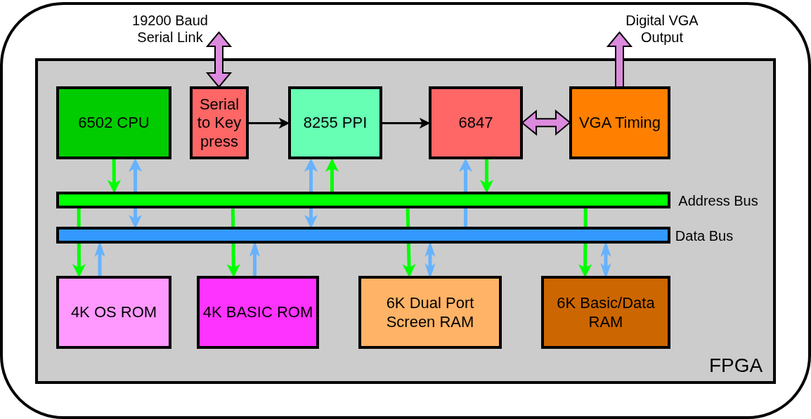
The Acorn Atom FPGA design consists of just a few components, my 6502 CPU design, two ROMs for the BASIC interpreter and the operating system, 12K of RAM, an 8255 PPI device, my 6847 video display generator, VGA timing and glue logic. The architecture of the system is shown below.
6502, 6847 and VGA Timing
The 6502 and 6847 are Verilog blocks I have previously developed and are described in the Classic 8 bit parts section of this website. The VGA timing block generates sync signals to output an 640x480 pixel 60Hz VGA image, into which the 256x192 6847 output is placed. The 256x192 pixels are doubled horizontally and vertically to better fill the VGA screen. The clock for the whole system is derived from the VGA pixel timing. A 640x480 screen at 60Hz requires a pixel rate of 25.2MHz which is then used as the main clock for the whole design.
8255 PPI
The Intel 8255 Programmable Peripheral Interface is a simple digital I/O device. In the Acorn Atom it is used to set control lines for the 6847, drive the speaker, scan the keyboard matrix and drive the cassette data storage interface. The 8255 PPI can operate in one of three modes but the Atom only used Mode 0 which is the simplest with 12 output pins and 12 input pins. The speaker and cassette interface are not supported in this design so very little verilog is needed to model the required behaviour.
Serial to Key press
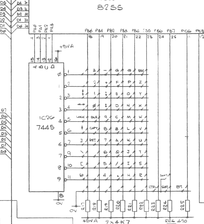
The FPGA Atom design has serial UART logic to allow communication with a PC. The screen output of the Atom is visible via the VGA display so the serial link is just needed to map input onto the Atoms keyboard to allow it to be fully controlled. One option would be to modify the operating system ROM code to remove the keyboard scanning code and replace it with code that reads data from the UART. This is the approach that Grant Searle used on his UK101 design which I also adopted on my UK102 variation. I didn't want to start fiddling with the OS code straightaway and so decided to try a different approach. The circuit snippet below shows the Atom's keyboard logic.
RAMs, ROM and Glue logic
The design features 6K of basic/data ram which is mapped to single port FPGA ram blocks using Verilog code to infer RAM behaviour. Similarly the 4K BASIC and 4K OS ROMs also map to single port FPGA ram blocks which are initialised with the required contents. The 6K screen ram maps to dual port FPGA ram blocks. Dual port rams are used to allow simple access to the data from both the 6502 processor and the 6847 display block. A timesharing arrangement could be used to enable dual access to single port rams but FPGA ram blocks are usually dual port anyway.
Software - Basic
The manual that came with the Acorn Atom 'Atomic Theory and Practice' has a few simple basic graphics programs that are short but quite effective.
A 3D mathematical function plot from the manual section '11.5.2 Three-Dimensional Plotting'.
Four colour graphics using the built in 6502 assembler from the manual section '11.9 Colour Graphics'.
A simple basic program written from scratch to display random characters on the text screen.